
The Sudbury Neutrino Observatory (SNO) is a new facility that has been constructed in Canada by a team of scientists from Canada, the United States and Britain. SNO will measure the flux, energy and direction of electron-neutrinos produced in the sun. The observatory will also be able to detect the other two types of neutrinos (muon-neutrinos and tau-neutrinos) which, if detected, would significantly alter our present understanding of neutrinos, the sun and the evolution of the entire Universe.
The image to the right is an aerial view of #9 shaft head at Creighton mine, where the SNO detector is located.
![]()
In the early 1980s, progress in theories of Grand Unification prompted the construction of several proton decay experiments. Grand Unified Theories (GUTs) hold that at a sufficiently high energy the three forces of nature would unify into one fully symmetric force. A consequence of this is that the proton (previously thought to be stable) would decay, but with a very long half-life.
The search for proton decay, and in fact the search for any naturally occurring exotic event, must be done in large detectors deep underground. The large size of the detector compensates for the rareness of the events, while the location deep underground shields from the high energy cosmic ray background. A proposal was made in 1983 for the construction of such a laboratory in INCO's Creighton mine near Sudbury, Ontario, which was selected due to the stability of the rock, the available infrastructure and the willingness of INCO management to consider the project. Several ideas were considered for the experimental program at the Sudbury site.
In 1984, Herb Chen at the University of California at Irvine presented a paper at the Homestake conference pointing out the advantages of using heavy water as a neutrino detector. Following discussions in Ottawa in September 1984 the SNO Collaboration was formed to develop a proposal to build a solar neutrino detector using some of Canada's large reserves of heavy water. The deuterium in heavy water enables the detection of all three types of neutrinos which might yield a solution to the Solar Neutrino Problem (SNP). Atomic Energy of Canada Limited (AECL) indicated that they would be willing to loan 1000 tonnes of heavy water while it was not required for new CANDU reactors. This would be an international Canada-U.S. project located in Canada, with spokesmen Herb Chen, UC Irvine and George Ewan, Queen's University.
NSERC produced funds in January 1985 for the initial collaboration to prepare a feasibility study. This was completed in July 1985 and funds were requested for a complete engineering design. In April 1986 an exploratory tunnel (drift) was excavated at Creighton's 6800 foot level, and a suitable site was found where a 20m diameter cavity could be constructed. NSERC funded the detailed proposal, which was submitted to NSERC and the National Research Council (NRC) in October 1987. This proposal was technically reviewed beginning June 1988 by an International Scientific and Technical Review Committee; which then recommended funding as proposed. Funding commitments were received from NSERC, the Northern Ontario Heritage Fund Corporation and the US Department of Energy in 1989. The cost of SNO was fully reviewed in November 1989, and final commitments received from the UK Science and Engineering research Council (SERC) and Industry Science and Technology Canada. In 1990 the SNO Institute was formed with Art McDonald, Queen's University, as the director.
![]()
Solution of the Solar Neutrino Problem (SNP), and in particular the investigation of neutrino oscillations, requires independent measurements of the flux of electron neutrinos (ne) and mu- and tau-neutrinos (nu and nt). SNO is unique in its ability to accomplish this. With heavy water we can measure the flux and energy spectrum of electron neutrinos (F(ne)) and the flux of all neutrinos (denoted F(nx)). The flux of non-electron neutrinos is then just the difference, ie.
F(nu and nt) = F(nx) - F(ne)
SNO can measure these fluxes via the different ways in which neutrinos will interact with the heavy water:

ne + d ----> p + p + e-
As the neutrino approaches the deuterium nucleus a heavy charged particle of the weak force (called the W boson) is exchanged. This changes the neutron in deuterium to a proton, and the neutrino to an electron. The electron, according to mechanics, will get most of the neutrino energy since it has the smaller mass (just as when a gun is fired, the bullet, being lighter, gets most of the energy). Due to the large energy of the incident neutrinos, the electron will be so energetic that it will be ejected at light speed, which is actually faster than the speed of light in water. This causes the optical equivalent of a "sonic boom", where a "shock wave of light" is emitted as the electron slows down. This light flash, called Cherenkov radiation, is detected by the photomultiplier tubes (PMTs); the amount of light is proportional to the incident neutrino energy.
From the PMT hit patterns the energies of the neutrinos can be determined and an angular distribution measured. The spectrum of neutrino energies will show a distortion from the theoretical shape if neutrino oscillations are occurring.
The Standard Solar Model predicts about 30 charged current events per day in SNO.

nx + d ----> p + n + nx
In this reaction the heavy weak force particle exchanged (called the Z boson) is not charged, hence the name "neutral current reaction". The net reaction is just to break apart the deuterium nucleus; the liberated neutron is then thermalized in the heavy water as it scatters around. The reaction can eventually be observed due to gamma rays which are emitted when the neutron is finally captured by another nucleus. The gamma rays will scatter electrons which produce detectable light via the Cherenkov process discussed above.
The neutral current reaction is equally sensitive to all three neutrino types; the detection efficiency depends on the neutron capture efficiency and the resulting gamma cascade. Neutrons can be captured directly on deuterium, but this is not very efficient and clearly distinguishing the spectra would be challenging. For this reason SNO is developing two separate neutral current systems to enhance the neutral current detection. The diagram to the right shows capture on 35Cl, which will be added to the heavy water in the form of NaCl during the second phase of detector operation.
The Standard Solar Model predicts about 30 neutrons per day in SNO.

e- + nx ----> e- + nx
This reaction is not unique to heavy water and it is the primary mechanism in other light water detectors. Although the reaction is sensitive to all neutrino flavours, the electron-neutrino dominates by a factor of six. The final state energy is shared between the electron and the neutrino, thus there is very little spectral information from this reaction. Good directional information is obtained.
The Standard Solar Model predicts about 3 electron scattering events per day in SNO.
![]()
At 6800 feet (2070m) below ground the SNO cavity in INCO's Creighton mine is the largest in the world excavated at this depth, requiring the latest advances in rock stabilization and ground control techniques. At this depth the rock is under a pressure of about 50 MPa (over 550 atmospheres or 8,000 psi).
Profile of INCO's Creighton mine, showing the location of SNO
The Sudbury basin is believed to be the remnants of a crater formed millions of years ago due to the impact of a massive meteor. The vaporization of the overburden rock resulted in copper and nickel rich magmas to flow up into the fragmented basin rim. Today copper and nickel are mined in between the norite "hanging wall" rock and the granite gabbro "foot wall" rock from rich ore deposits that slope toward the basin centre. The SNO site is located in the "hanging wall" rock 200m from the mining zone to minimize interference from blasting or rock burst activity.
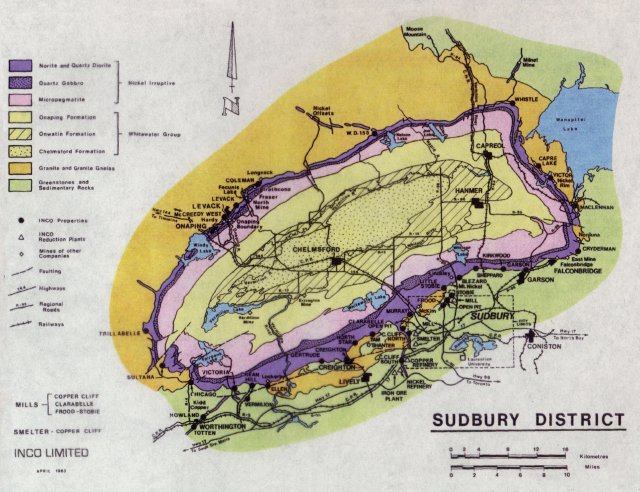
Geology of the Sudbury area
The site had an extensive geo-technical evaluation using micro-seismic transducers and computer modeling of the rock stresses. The cavity design, incorporating large safety factors, was barrel shaped and stabilized by some 800 "cable bolts", each cemented 30 feet into rock.
The excavation began in March 1990 and was completed in May 1993. The procedure was to blast out 15 foot benches and shovel the rock down a central hole, where it was scooped out via ramp access. Over 60,000 tonnes of rock was blasted, trammed and hoisted to the surface. Throughout the excavation cable bolts were installed with bolted steel screening and sprayed concrete.
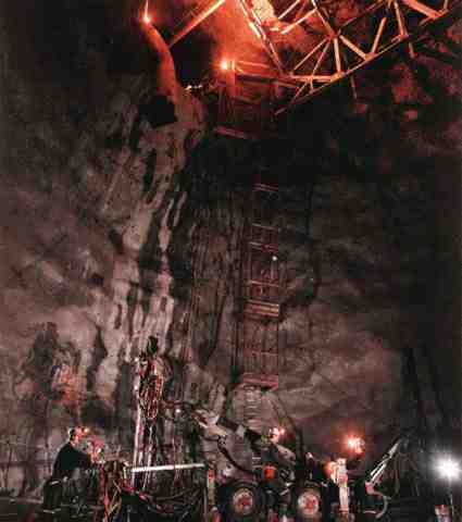
Drilling the last bench in the SNO cavity
A steel deck support structure was erected and the cavity walls were covered with a polyurethane liner. The lab has concrete floors, water and electrical service and air handling. By early 1995 the lab had been thoroughly cleaned and the detector construction under clean-room conditions had begun. The rest of the construction was completed under clean-room conditions and the detector filled with heavy water.
![]()
The photomultiplier tubes (PMTs) are the eyes of the detector. PMTs are very sensitive light detectors, capable of sensing single light photons and producing an electrical pulse that travels to the data acquisition electronics. The PMTs consist of high voltage dynode plates within an 8" glass bulb. Light photons interact with a thin film on the inside of the glass to eject an electron. This electron is accelerated towards the high voltage plates where it causes a cascade of electrons to produce the pulse. SNO has 10,000 of these PMTs so that we can collect as many of the photons as possible from the Cherenkov light that results from the neutrino reactions.

Phototubes with reflectors installed in a hex panel
Due to the sensitivity of the detector the PMTs had to be of the highest quality, both in terms of performance and cleanliness. The glass bulbs were blown in Germany from special UV-transparent, low-radioactivity glass, then shipped to Japan to have the high voltage dynodes installed. Installation of the base electronics, cables, connectors and final assembly was done in the physics department at Queen's University, Canada. The PMTs then underwent stringent testing at Queen's to ensure that the PMT gain, noise rate and efficiency was acceptable.
The nitrogen laser testing system
The PMT testing consisted of water tests, vacuum and mechanical tests and then the performance of each PMT underwent 18 hours of evaluation with the Queen's computerized nitrogen-laser test system (see figures). Over 10,000 PMTs were assembled and tested.
Testing results for one of the 10,000 PMTs
![]()
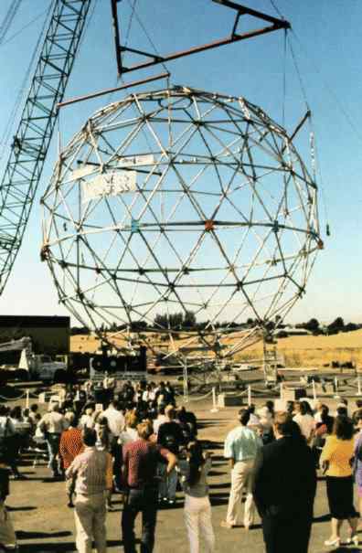
a) Final test assembly of the PSUP at LBL b) PSUP installed in mine
![]()
The heavy water is contained inside a 5-cm thick transparent acrylic vessel, submerged in light water. The vessel is suspended from ropes so that the PMTs are unobstructed and to provide damping in the case of rock bursts or other ground movements. The vessel is a 12-m diameter sphere with a 8-m tall neck section (2-m diameter) to provide access for filtering pipes, calibration devices etc.

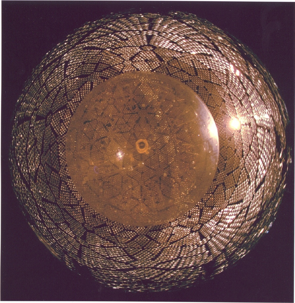
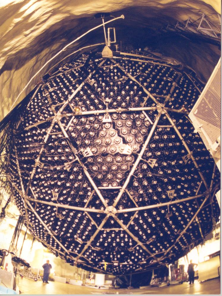
a) Dry test assembly of upper-half acrylic vessel panels b) Installed vessel viewed from below inside SNO PMT sphere
The vessel was assembled and bonded underground from 125 pre-formed panels (since all detector components must fit into the mine hoist cage). The panels were manufactured by Polycast Inc. and then thermoformed by Reynolds Polymer Technology (Grand Junction, Colorado) to very strict quality standards to ensure high ultra-violet transparency and very low levels of ordinary background radioactivity. The assembly of the acrylic vessel was completed in November 1997.
![]()
The SNO electronics task is extensive. The signals from each of the 10,000 PMTs need to be individually processed, involving charge amplification and discrimination, analogue to digital conversion, time to digital conversion, analogue and digital buffering and multiplexing I/O tasks. Each PMT channel must have a very large dynamic range (0.1 to 1000 photoelectrons), timing precision to better than 1 nano-second, have a very fast reset time and be able to buffer data to handle event burst rates of 100's of kHz. Additionally, the power consumption must be low due the lack of heat sink capacity in the mine.
Groups of 32 PMTs connect to a Front End Card (FEC), designed at University of Pennsylvania, to process the PMT signals and distribute the high voltage. At the heart of the FEC is the analogue/digital storage array, an in-house chip design using the latest CMOS technology. The chips were designed at University of Pennsylvania and at Queen's University and were manufactured at Northern Telecom Ltd. in Ottawa.
Sixteen of these FEC cards then plug into a VME crate controlled by a single board computer (SBC). The SBC handles crate monitoring, on-line diagnostics and local event trigger logic. There are 20 of these VME crates which in turn are controlled by the data acquisition computer (DAQ) via a custom highspeed data protocol. The DAQ serves as the master trigger controller and event builder. The DAQ writes data out to several mass storage devices both in the mine and on the surface by fibre-optic links. The DAQ also communicates to the calibration computer, water systems and the CMA computer. The DAQ system is being developed at the University of Washington with assistance from other SNO institutions.
![]()
The water systems in SNO must be able to maintain very large volumes of water at unprecedented levels of purity. In particular, elements from the Uranium (U) and Thorium (Th) radioactive chains must be reduced to concentrations a million times lower than is found in natural water. If radioactive elements decay in or near the detector the signal could be large enough to be indistinguishable from a neutrino event. The purpose of the outer light water is to provide a medium for absorption of gamma rays and neutrons that result from activity within the rock. For the 1000 tonnes of heavy water, impurities must be less than 10-14g/g of water, while for the 7000 tonnes of light water the levels must be maintained at less than 10-13g/g of water.
All detector materials that come into contact with the water have been carefully analyzed and selected for low radio-impurity levels and low rate of impurity "out-gassing". (For example, it is well known that many plastics "out-gas", that is why they often smell). Even then, the water systems will need to purify water at a rate of 100's of liters per minute. The purification systems must also prevent any biological activity in the water, as this could severely compromise the UV transmittance of the water.
The purification systems use a large variety of techniques, resulting from extensive research at Carleton University, Oxford University, Queen's University, AECL and the University of Guelph. The main components are large high pressure reverse osmosis units, seeded ultra-filtration, ion-exchangers, ultra-violet sterilization and vacuum degassing. Specialized filters and complexing agents have been developed to remove particular elements and to provide for impurity monitoring. Lead and MnO2 bead filters have been developed for extraction of Uranium and Thorium derivatives, and for water quality assay.
A major function of the D2O water system is to add and remove a large volume of salt. Controlled quantities of salt will be added to the D2O as part of the neutral current detection. The Chlorine in the salt is a strong absorber of neutrons, which are the signal of a neutrino reaction in the neutral current channel. The system must be able to remove two and a half tonnes of salt within a couple of water cycles in order that the detector transient time is minimized. A high efficiency salt extraction technique has been developed at Carleton University and Chalk River Laboratory, while Oxford University has researched salt purification techniques.
![]()
The neutral current reaction in heavy water liberates a neutron which is thermalized in the heavy water and observed following capture on other nuclei within the detector. The neutral current rate will be the number of neutrons above background levels, after correcting for the capture efficiency. The thermal neutron capture efficiency on deuterium is not large (about 25% for capture with the D2O volume) so SNO will have two systems for increased neutral current efficiency.
The neutral current detectors (NCDs) are Helium-3 (3He) proportional counter tubes hung in a grid within the D2O. 3He has a very large cross-section for the capture of thermal neutrons, which produces an energetic proton-triton pair resulting in an electrical pulse in the counter wire. Some 800 meters of tubes will be deployed uniformly throughout the D2O in strings up to 11m. Owing to the large volume of tubing the counters must be fabricated from ultraclean materials. The tubes were initially manufactured by Mirotech Ltd., and are now being made by CVD Manufacturing, Inc. of Toronto, by a special chemical deposition process that produces ultrapure nickel. Levels of uranium and thorium will be less than several parts per trillion by weight. The NCDs will be deployed part-way through the SNO program using a remote controlled submersible vehicle. The NCDs are under development at the University of Washington and Los Alamos National Laboratory.
The salt option is to load the heavy water with over two tonnes of salt (NaCl). The chlorine (35Cl) has a high absorption cross-section for thermal neutrons, resulting in a gamma ray cascade peaked at around 8 MeV. The neutron capture efficiency will be about 83%. The background for this process will be neutrons produced by photodisintegration of the deuteron, arising chiefly from the 2.45 MeV and 2.63 MeV gamma rays in the 232Th and 238U chains. Special care will be taken so that the salt is at the highest level of cleanliness.
![]()
![]()
Calibration of the detector is an integral part of data acquisition process and the most important aspect of the analysis. Essentially the calibration converts detector data (number of PMTs that fire, their location and time) to an event energy and direction. This conversion is complicated because the sensitivity of the detector is position dependent and is different for electrons, gamma rays and neutrons. The calibrations must be frequently updated due to the possibility of drifting PMT gains and changes in the detector condition.
Ideally for calibration, one would use a strong portable source of high energy neutrinos. Since such a source is not possible, calibrations must be obtained by other means. The calibration of SNO will involve several redundant techniques using optical photons, gamma rays and beta sources until the detector is fully characterized.
Optical CalibrationAn optical calibration is required to monitor the optical condition of the various detector regions and to check the gain and efficiency of the PMTs.
The primary optical source is a nitrogen/dye laser system that has been developed at Queen's university. A fast (600psec) nitrogen laser beam is used to pump one of several dye units, allowing us to generate light at a variety of optical wavelengths between 337 nm and 620 nm. The acrylic vessel absorbs quite strongly at a frequency of 337 nm, and the light water becomes absorptive at 620 nm. The beam is then delivered into the detector via special silica optical fibres terminated by an isotropic scattering ball. The scattering ball can be located at a large variety of positions in two perpendicular planes using the manipulator system.
Gamma Ray CalibrationGamma ray sources are used to provide mono-energetic calibration points. Gamma rays are especially useful because they provide sources with very well defined energies. They are also useful because they penetrate into the water before scattering, and therefore they are not significantly shadowed by the source itself. There are several sources under development:
Our absolute energy calibration, which is used to determine the absolute quantum efficiency of our photomultiplier tubes, is a 16N source. This source is also used to test the optical calibration by checking to see that the variation in energy with position is correctly predicted with the parameters derived from the laser measurement. In addition, the source is deployed periodically to ensure that detector parameters (either electronic or optical) are not changing as a function of time.
This source was developed by AECL, Berkeley, and Queen's. It uses a flow of carbon dioxide gas past a commercial d-t neutron generator, which provides a flux of neutrons to initiate the reaction n(16O,16N)p. The dt generator is located away from the cavity (in an area we call the "junction"). The 16N flows through tubing to the deck clean room, and then through an umbilical to a decay chamber that can be deployed by the source manipulator. 16N is a beta emitter with a 10.42 MeV end-point branch followed by a 6.13 MeV gamma. The decay chamber will be thicker to shield the electrons, allowing the gamma to pass through for use as a calibration point. The 16N half life is 7 seconds.
The University of Washington, University of British Columbia, and Berkeley have built a 3H(p,gamma)4He source producing 19.8 MeV gamma rays. This source has been deployed in several positions along a vertical axis inside the SNO detector.
Queen's University and Berkeley have developed a source based on an activated NaI crystal. The beta-gamma decay of 24Na allows for gating on the positron with a small PMT while the gammas yield a 2.8 MeV and a 1.4 MeV calibration.
Electron CalibrationThe electron calibration will be accomplished with a 8Li beta decay source. 8Li has a beta branch which is similar to the 8B neutrino spectrum; the end-point is about 13 MeV and the half-life is 0.838s. The isotope will be created via 11B(n,alpha)8Li in a strong neutron source located away from the detector. An He-NaCl aerosol gas capillary will rapidly transport the isotope to a thin walled transparent acrylic decay chamber within the D2O. Distortion due to the chamber will be about 250 KeV. This source was developed by a team from Guelph, AECL Chalk River Laboratory, Los Alamos, and Queen's University and has been deployed in the SNO detector.
Neutron SourceA source of neutrons is required to calibrate the efficiency of the neutral current proportional counters (or the salt). Los Alamos National Laboratory has constructed a variety of 252Cf sources. These have been deployed throughout the detector to measure the neutron capture efficiency and to test the energy response.
The gas transport system discussed above can also produce 17N which emits neutrons with low energy beta-gammas.
The Manipulator SystemThe manipulator system is a fully automated rope and pulley arrangement. It was developed and has been constructed at Queen's University, to maneuver sources within the detector. All the sources that are deployed use this mechanism, which allows the controlled positioning of sources within two perpendicular planes in the detector, and along 6 vertical axes in the light water volume.
|
|
|
URL: sno/sno2.html (Last revised Jun 26, 2002)
Mail problems/comments to qusno@sno.phy.queensu.ca |